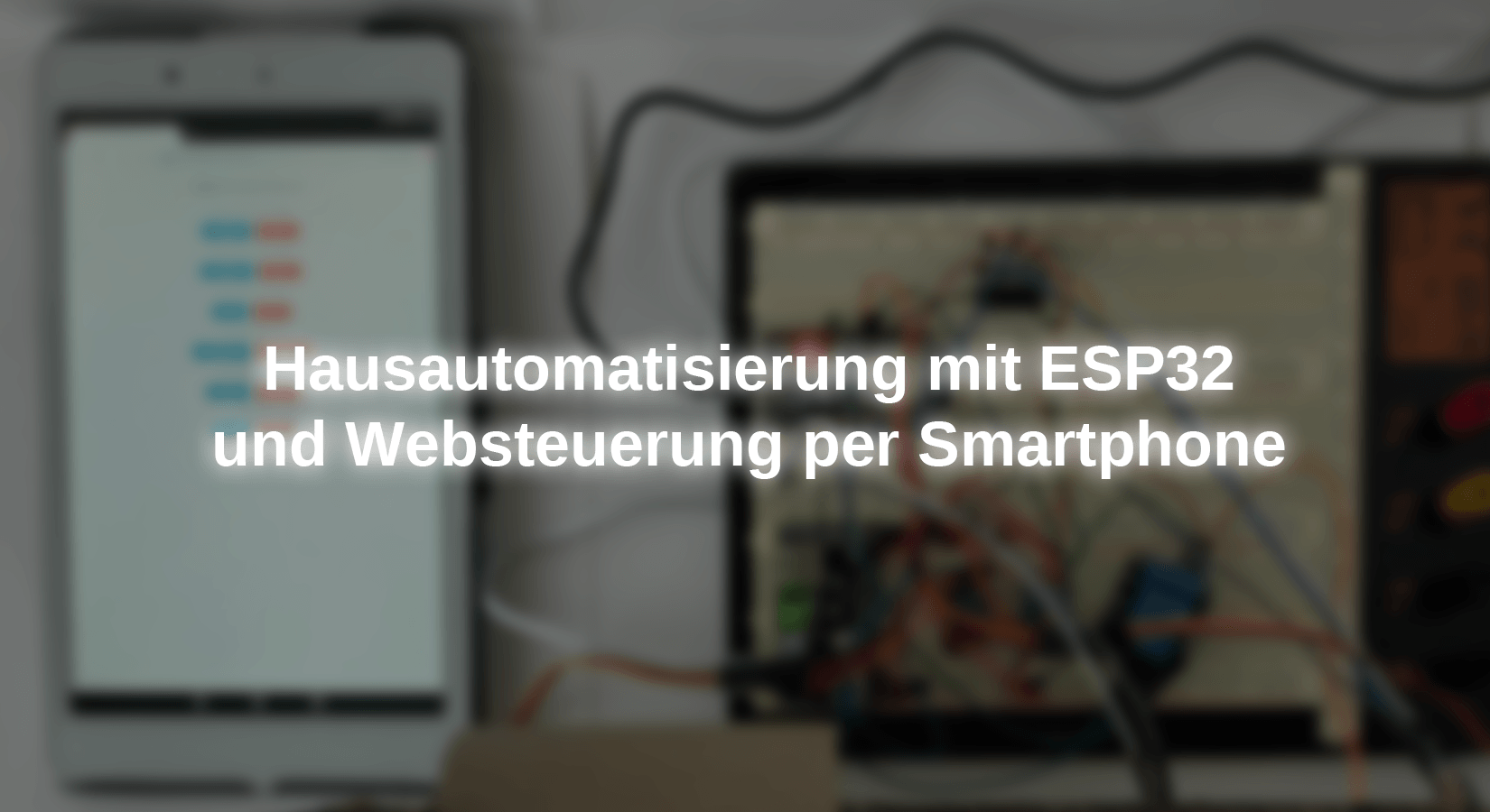
In this project we will use our local WiFi network to control elements of our house on our mobile phone, e.g. B. a roller shutter, the lighting, the fan in a room, the garage door, or the awning in our garden. We will use components for a model house, but the basic principles of the project can also be developed for implementation in real cases.
We will control two DC motors with the development board ESP-32 Dev Kit C V4. One of these engines is connected via the integrated circuit L293D. This can change the direction of rotation and thus move a blind up and down. The other engine turns a fan. We also control two SG90 service engines for the garage door and the drive of an awning. We will use an LED for the lighting of a room. With the help of a logic level converter such as the TXS0108E, the voltage is adapted to the 5V operating voltage of the components. If we wanted to implement this project in a real case, we would have to use a relay board because the components are connected to the 230V network. To control the elements, we will use a mobile phone or tablet that connects via WiFi to the ESP32 which acts as a web server.
Used Components
|
1 |
|
|
2 |
|
|
1 |
|
|
1 |
|
|
2 |
|
|
1 |
|
|
1 |
|
|
1 |
|
|
1 |
|
|
|
The electronics of the super starter kit contain several of the above components of The electronics of the super starter kit. |
Used software and files
- Wifi.h library (integrated)
- Espasyncwebserver.h Library (library manager)
- The Espasyncwebserver Library needs the Asynctcp Library (library manager)
- Spiffs.h library
- ESP32Servo.h Library (library manager)
Circuit Diagram

The circuit is controlled via the ESP32 development board. Its GPIO ports have an output voltage of 3.3V. We have to use a logic converter like the TXS0108E to deliver the 5V to the components (in this project I use two 4-channel logic converters). The LED, which simulates the lighting, is connected directly to GPIO 19 because it provides the right voltage for it (3V). In order to control the direction of rotation of the blind motor, we have to use the integrated circuit L293D, which is controlled via GPIO ports 32 and 33. The fan motor only turns in one direction. He is connected to a relay after the converter to avoid impedance problems with GPIO port 14. GPIO Port 22 controls the garage gate servomotor, while GPIO Port 23 controls the awning service. The signal lines of the servomotors are connected to the outputs of the converter.


In order to control the various elements, we have to connect via WLAN to the ESP32 development board, which will act as a web server. For this project, the necessary files for the graphical environment (HTML page and CSS file) from the Arduino sketch are separated. The two additional files have to be used with the "SPI Flash File System"Deloaded into the ESP32 file system. You have to have "ESP32 File System Uploader" installed in the Arduino IDE.
Description of the program codes (Ino, HTML, and CSS)
From the cell phone or tablet, the IP of the ESP32 board is called up in the internet browser. The address is output in the serial monitor. It will never change for this ESP. After the call, the website is displayed with buttons with which you can select the desired action for each component. The status or the action carried out is also displayed.

To create the website, we first create the stylesheet style.css, the file with the design features of the texts and buttons.
In the block with the HTML tag we configure the font (Helvetica), the text block (inline-block), the distances (margin) above and below (0PX), as well as the pages (automatic). In addition, the text is shown centered (text-align).
HTML {
  Font family: Helvetica;
  Display: inline-block;
  margin: 0px automobile;
  text align: center;
}
In the block with the designation H1 the values for headings with the black text color, the distance from the edge must be at least 1 % of the screen's height and configured with the text size of 20 pixels.
H1{
  color: Black;
  padding: 1vh;
  font-size 20px;
}
For text that is provided with the P-Tag, the font size is 1 rem, which corresponds to 16 pixels in HTML.
P{
  font-size 1rem;
}
In order to define the values for the buttons, we place values for button and Button2 firmly. The second inherits all unchanged values of the button. The buttons located within the same block are shown on the same line. The color will be green (we define you with the hexadecimal value #008CBA), the edge of the button is not drawn, the rounding of the corners of the button will have a radius of 4 pixels, the color of the text of the buttons will be white, the distance from the upper and lower edge of the text to the edge of the button is 6 pixel And the pages 30 pixels. There is no graphic effect, the size of the text is 15 pixels, and the free space around the buttons is 2 pixels with one Cursor: pointer A pointer is displayed if you move the mouse via the button. The only value that is for Button2 Differentiates from the previous ones, the color of the button is. It is displayed in red and also defined with a hexadecimal value.
.button {
  Display: inline-block;
  background-color: #008CBA;
  border: none;
  Border radius: 4px;
  color: white;
  padding: 6px 30px;
  text-decoration: none;
  font-size: 15px;
  margin: 2px;
  cursor: pointer;
}
.button2 {
  background color: #f44336;
}
The file now follows index.htmlthat contains the website with the titles and buttons. They appear when you enter the IP address in the browser. Let us state that it is an HTML document. The -Tag contains information on the presentation of the page in browsers that



9 comments
Andi
Ich glaub hier ging es eher um die Veranschaulichung, wie man etwas am Handy über einen Webserver steuern kann ;-)
Andreas Wolter
@PK: Wir haben den Schaltplan ersetzt. Danke für den Hinweis.
Grüße,
Andreas Wolter.
AZ-Delivery Blog
i.A. Miguel Torres Gordo
Miguel Torres
Hello Peter,
I tried to reproduce the error and it didn’t appear, I tried with two ESP32 and it loaded both files fine in both of them.
When you loaded the sketch, did you get the reset message: "Hard resetting via RTS pin…, before trying to load the html and css files?
Try resetting the ESP with the physical switch of the module after loading the sketch and before loading the html and css files.
I have searched the internet and found this address https://github.com/me-no-dev/arduino-esp32fs-plugin
Download the file from the “releases page” and follow the installation instructions.
Best regards
Miguel Torres Gordo
Miguel Torres
Hello Martin,
I haven’t explored that communication protocol, but I’m writing it down to do some research and see about the possibility of realizing a project.
Best regards
Miguel Torres Gordo
Miguel Torres
Hello Samba,
I agree that all projects can always be improved, in this project, in addition to drive some components from a mobile device, also explains how to use an ESP as a web server and what is the process of implementing it, so this project can also serve as an initial idea to improve it By adding new components and features.
Best regards
Miguel Torres Gordo
Peter
Ich bekomme beim Hochladen der index un der css folgenden Fehler: SPIFFS Not Supported on esp32
Martin
Vielen Dank für das coole Projekt. Wenn ich es richtig verstehe, gibt es einen MC der über das Web alle Aktuatoren steuert. Im schlimmsten Fall müssten dann durch das ganze Haus ja dahin Kabel gelegt werden. Gibt es auch einen Lösungsansatz , wo über einen Master (der über die Web Seite gesteuert wird) die fern stehenden Aktuatoren OTA gesteuert werden (also mit mehreren Slaves)???
PK
Hallo, im Schaltplan fehlt die positive Spannungsversorgung am ESP ….
Gruß PK
Samba
Moin moin,
ich muss ja sagen, ihr bekommt mich durch die Newsletter unheimlich häufig zu lesen der Blogeinträge, oder auch zum kaufen von einigen Komponenten :-)
Allerdings ist es für mich unverständlich in einem “Hausautomatisierung” Projekt keinerlei Automatisierung vorzusehen. Es wäre doch viel besser gewesen die Rollladen per Lichtsensor zu steuern und den Ventilator per Temperatur und Anwesenheitssensor.
Hier wird einem ja nur der Tastendruck erspart und es gibt dabei nicht einmal ein Feedback, auf welchem Niveau die Rollladen stehen" Nach dem ich hier viel im Blog lese, weiss ich auf jeden Fall das ihr es besser könnt ;-)