When I start a project, I think first about which microcontroller I will use. My first thought is to use an ATMEGA328 board. Either the AZ-ATMEGA328 version or the Az-Nano V3 because they are easy to handle because they are compatible with the Arduino IDE programming environment that I have got used to and because a variety of libraries and codes are available for the additional components. However, there are some alternatives, such as the ESP product range, or Raspberry PI. For various reasons, it makes sense to rely on another microcontroller.
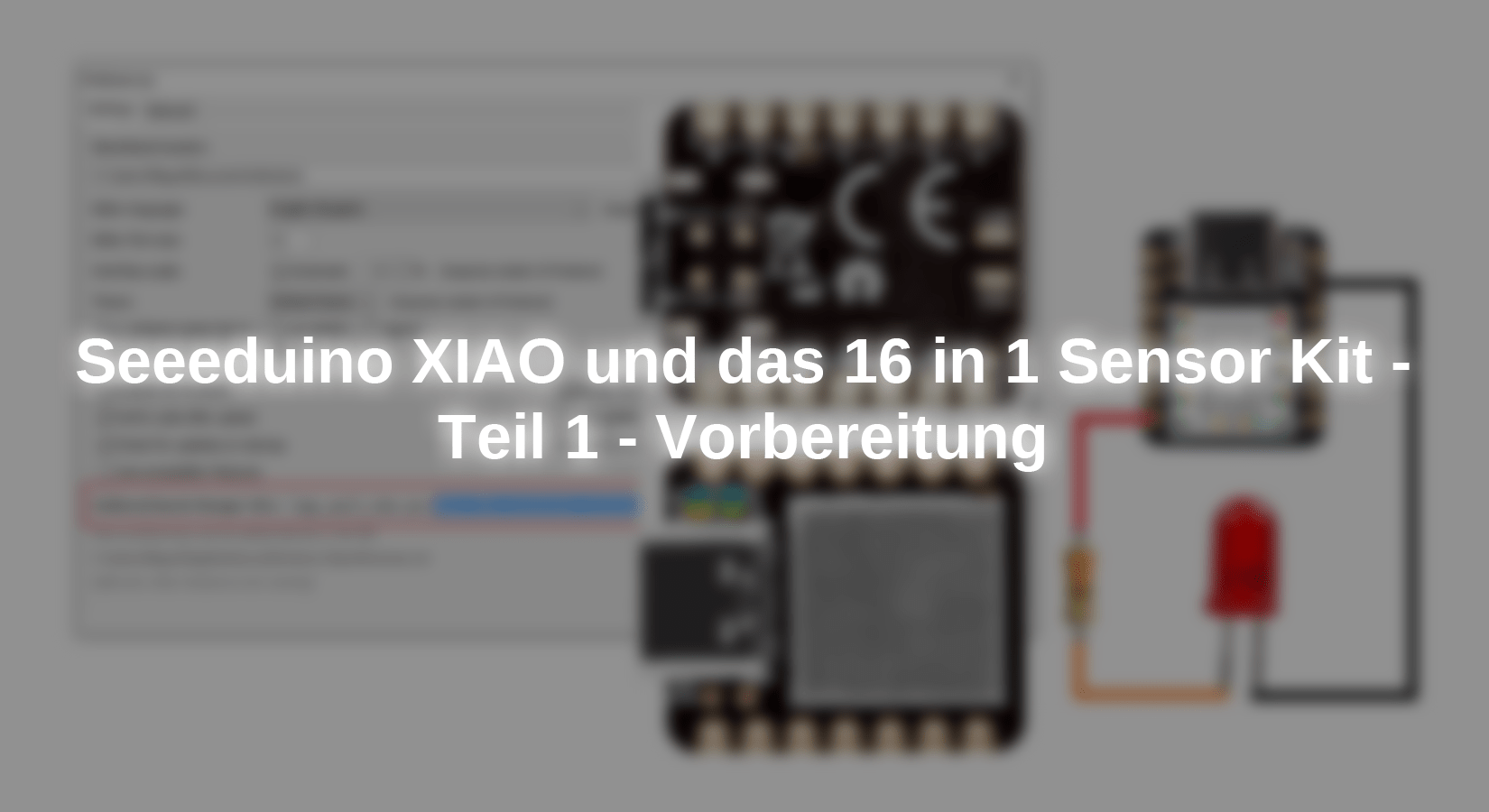
In this blog series that should Seeeduino Xiao Microcontroller board can be used. It has more performance and performance with significantly lower dimensions than the ATMEGA328P boards. This is ideal for creating new projects for portable devices or simply projects with small dimensions.

Before we go on his description and work with him, we want to compare some data with the other two boards mentioned.
|
|
Seeeduino Xiao |
Az-Nano V3 |
AZ-ATMEGA328 |
|
CPU |
ARM Cortex-M0+ CPU (Samd21G18) with up to 48MHz |
ATMEGA328 with 16MHz |
ATMEGA328 with 16MHz |
|
Memory |
256kb flash, 32kb sram |
32kb flash, 2kb sram |
32kb flash, 2kb sram |
|
I/o pins |
11 digital pins, 11 analog pins |
22 digital pins, 6 analog pins |
22 digital pins, 6 analog pins |
|
PWM output |
10 pins PWM |
6 Pins PWM |
6 Pins PWM |
|
ADC |
11 Pins (12 bit) |
8 pins (10 bits) |
6 pins (10 bits) |
|
DAC |
1 PIN |
- |
- |
|
interface |
1 i2c interface, 1 uart interface, 1 spi interface |
1 i2c interface, 1 uart interface, 1 spi interface |
1 i2c interface, 1 uart interface, 1 spi interface |
|
Input Voltaje |
3.3 - 5 V |
7 - 12 V |
7 - 12 V |
|
Operating Voltage |
3.3 V |
5 V |
5 V |
|
LEDs |
1 user LED, 1 Power LED, 2 Serial Port Download LEDs. |
1 user LED, 1 Power LED, 2 Serial Port Download LEDs. |
1 user LED, 1 Power LED, 2 Serial Port Download LEDs. |
|
Power pads |
For Power Supply |
- |
- |
|
Software Compatibility |
Ide Arduino OK |
Ide Arduino |
Idea Arduino |
|
Dimensions |
20 mm x 17.5 mm |
18 mm x 45 mm |
70 mm x 55 mm |
The microcontroller on this small board is the 32-bit Atmel Cortex M0+ microchip. A 32-bit single-core processor with a clock frequency of 48 MHz. It has 256 kb flash memory and 64 kb SRAM, so it has a higher performance with a lower size. It is a small module with 14 starting spins and other connections via pads on the surface. The labeling of the pins on the board begins at 0, so that the pins on the board match the numbers of the connections of the digital and analog input and output pins. The respective pins have several functions that I will describe here.
Voltage supply to the module
The microcontroller can be operated with 3.3V and 5V because it has an integrated DC DC performance converter XC6206P332MR.
This Seeeduino Xiao module can be supplied with electricity in 4 different ways:
- About the USB-C connection with 5 VDC.
- With 5 VDC to PIN 13, which is labeled with VCC.
- 3.3 VDC can be created directly on PIN 11 of the module.
- At the underside of the module we have the PADS VIN and including the PIN GND, to which we can connect a voltage of 3.7 VDC to 5 VDC. A Lipo battery could be connected to these connections.


Another special feature of the Module is that pins 11 and 13 can be used as inputs or outputs. If the voltage is used By the USB-C connection, PIN 11 can be used as a 3.3 VDC output and PIN 13 as a 5 VDC output.
If the 5 VDC voltage is created on PIN 13, PIN 11 can be used as 3.3 VDC output. But if the module is supplied with 3.3 VDC via PIN 11, PIN 13 can not used as 5 VDC output. PIN 12 is the mass connection (GND) of the module. As usual, all mass connections of the components used must be connected to each other in order to obtain the same reference.
Analog inputs
The Seeduino Xiao microcontroller has a total of 11 analog input pins, from pin 0 to pin 10. Each PIN is connected to a 12-bit analog digital converter. The maximum voltage that we can use on any PIN is 3.3 VDC. The creation of a higher voltage than 3.3 VDC leads to the destruction of the pin or the microcontroller itself.

Digital inputs and outputs
The same 11 pins as above can be used as digital input and output pins. The maximum working voltage is also 3.3 VDC. This tension is also sufficient for most modules and sensors on the market. If we use sensors or modules that work with a voltage of 5 VDC in the data signal, we need to have a logic level converter like the TXS0108E interlock.

Connections for pulse width modulation (PWM)
Like the ATMEGA328 microcontroller, the Seeeduino also has PWM connections, exactly 10 from pin 1 to pin 10.

Connection for digital analog converter
PIN 0 is the outcome of the digital analog converter. It creates a pure analogue signal from 0 to 3.3 VDC.

Data connections
As mentioned, this board has a USB-C connection to connect it to the computer and upload the sketches. In addition, it also has interfaces for I2C, UART and SPI communication. The pins of the individual interfaces are the following:
- I2C: PIN 4 (SDA) and PIN 5 (SCL).
- Uart: PIN 6 (TX) and PIN 7 (RX).
- Spi: PIN 8 (SCK), PIN 9 (MISO) and PIN 10 (Mosi).

The top of the module
On the top of the Seeeduino Xiao module there are four LEDs and two pads to reset the module. LED L is yellow and is connected to the internal D13 pin of the microcontroller as with Atmega328 boards. So you can use the flashing sketch for testing. The LED P is green and lights up when the module is under tension. The LEDs T and R are blue and lights when data is sent and received via the USB-C connection.
To reset or restart the module, we have to short-circuit the two pads next to the USB-C connector with a cable, one of which is printed with RST.

Underside of the module
There are 6 pads on the underside of the Seeeduino Xiao module. The pads VIN and GND can be used as an alternative power supply. The pads RST and GND, which are used to reset the module, duplicate the functionality on the top of the module. The SWCLK and SWDIO pads are used for the debug function.

Preparation of the Seeeduino Xiao
When we the microcontroller from AZ-Delivery Received, we find two small bags. One of them is the microcontroller board and the other are the two pin rows that we can solder to the board. As soon as we have soldered the pins, we connect the Seeduino Xiao microcontroller board to our computer and test whether the green LED illuminates. The yellow LED should flash, as I said, it is connected to the internal pin D13. The flashing sketch is already pre-installed at the factory. If this is the case, congratulations, then you are ready at the hardware level to continue with the next step in which we have to install this microcontroller module in the Arduino IDE.
Installation of the Seeeduino module manager in the Arduino Die
To install the Seeduino module manager, first open the Arduino programming environment (Arduino IDE), then select "File" (file) and in the "Preferences" dropdown menu (default settings.
The setting window opens and in the section "Additional Boards Manager URLS:" (additional board administrator URLs) we have to download address
https://files.seeedstudio.com/arduino/package_seeeduino_boards_index.json
add. This address is the repository of the Seeeduino Module Manager, from which the Arduino Ide is looking for available boards in order to be able to select it later.


If the text field is empty, simply copy the address from the sea eduino module manager and insert it into this field, click OK.
If you already have another address in this text field, you can add it By either If you already have another address in this text field, you can add it By clicking on the button on the right. A dialog box opens in which you can add further addresses of microcontroller board managers that have to be added below the last existing ones. Click OK in both fields and you have added the sea eduino Module manager. You can now select the Seeduino Xiao Module as described below.
Installation of the Seeeduino Xiao module in the Arduino IDE
As soon as we have installed the module manager in the Arduino IDE, we can take the last step. Click on "Tools" (tools) when the drop-down menu opens, we have to go to the "Board: XXXXXXX" option, so that another drop-down menu appears where we "Boards Manager .. . "(Board administrator) must select.

A window opens. In the text field next to "Type", enter "Seeeduino Xiao", the installation package "Seeed Samd Boards By Seeeduino Studio" appears, click on the "Install" button.
The installation of this package can take some time, so you have a little patience because we are almost finished. When the installation is complete, the "Installed" library would have to appear. Click the "Close" button.


Now we have installed our Seeduino Xiao module. To check whether we have successfully completed the process above, click on "Tools" (tools) and in the dropdown menu on "Board: XXXXXXX", whereupon all modules we have installed are displayed. Depending on the Arduino IDE version you use, the presentation may differ somewhat.

Select the Seeduino Xiao board. Connect the module with a USB-C cable (make sure that the cable is not only a power cable, it must also be able to transmit data) to your computer. Check whether the green LED lights up and the yellow LED flashes. Now click on "Tools" (tools) again to display the options and scroll down to "Port". Click to open the dropdown menu and select the COM port to which the Seeeduino Xiao module was connected. The COM port number can vary here. This creates communication with your microcontroller.

Our first program: "Hello world" in hardware
When programming, the first program you learn is the "Hello World!" That appears on the screen. As we already know, the "Hello World!" In the world of the microcontrollers there is to flash or light up an LED. The first sketch that we will upload is the famous "blink.ino". We open file -> Examples -> 01.basic -> Blink. You can change the time when the LED is switched on or off By the value of the delay in Delay (1000) change. The value between the brackets is given in milliseconds, so 1000 are 1S.

Then click on the symbol  Or under "Sketch" to upload, or press the key combination Ctrl+U to load the sketch onto the sea eduino microcontroller.
Our first circuit - connection of a red LED

The first circuit that we will create is the control of an external LED with the flashing sketch. To do this, we switch on a 330-ohm resistance in series with a red LED, connect it to the digital pin 6 and set a break of 200 milliseconds between changes in the condition of the pin. If the Seeduino Xiao module is connected to the computer via the USB-C cable, we load the sketch onto the microcontroller. First the code is compiled and then (if there are no errors) is loaded onto the microcontroller. In the picture below you can see the messages that the Arduino die indicates:

Now that we have our microcontroller in operation, we can implement projects with this small module. In the next articles we will be the sensors of the AZ-Delivery 16 Test in 1 kits together with the Seeduino Xiao and check the compatibility of this microcontroller when using the sensors.
