These instructions are also available as PDF document
The IR trigger works quite well for the Nikon from a distance of one to two meters. Reading the setting is also ok, even in the dark, thanks to the OLED display. Sometimes, however, a much larger distance would be even better, for example in the case of recordings of Scheuer animals.

Image 1: The WLAN Connection-UDP client and UDP server
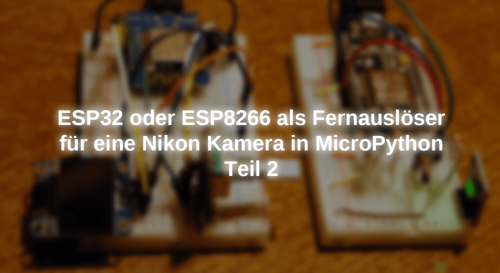
To enlarge the range, we share the circuit from the first part Simply open on the subject of Nikon-Timer. An ESP8266 D1 Mini, as in Figure 1, is done, as in Figure 1, the IR radiator is served By a second one or another relative from the ESP clan. We establish contact between the two via radio via WLAN and UDP. And because that should also work in Pampa, we need an island solution without a local house network. That means we will be at the second ESP8266, I have one here Amica In operation, activate the system's own access point and put a UDP server on it. The other ESP8266 plays the client and dials in the server. Incidentally, there is beginner information on Micropython again. So welcome to a new episode from the series
Micropython on the ESP32 and ESP8266
today:
Photo timer with remote control
How to read out an IR remote control, I have in the first part Described in detail, as well as reproducing the IR impulses By software. The program from this post is divided between the client and server today. This is done in a form that further ideas can be implemented as seamlessly as possible in subsequent projects. Let's start with the hardware. All parts from episode 1 are back in use. In addition, another ESP32 or ESP8266, two resistors, and a small performance PNP transistor.
Hardware
|
2 |
D1 Mini Nodemcu with ESP8266-12F WLAN module or Nodemcu Lua Amica Module V2 ESP8266 ESP-12F |
|
1 |
|
|
1 |
|
|
1 |
|
|
1 |
|
|
1 |
Resistance 100 Ω |
|
1 |
Resistance 1kΩ |
|
1 |
PNP transistor BC558 similar |
|
various |
|
|
1 |
Breadboard kit - 3 x 65stk. Jumper Wire Kabel M2M and 3 x mini Breadboard 400 pins |
|
1 |
Logic Analyzer optional |
ESP32 or ESP8266 are both suitable for this project with one exception. The exception is the ESP8266-01 because the simply too little GPIO lines has too little.
The software
For flashing and the programming of the ESP32:
Thonny or
Saleae -Logic analyzer software for Windows 8, 10, 11
Used firmware for the ESP8266/ESP32:
Please choose a stable version
ESP8266 with 1MB Version 1.18 Status: 25.03.2022 or
ESP32 with 4MB Version 1.18 Stand 25.03.2022
The version number is crucial for the implementation of the project.
The micropython programs for the project:
oled.py OLED frontend
SSD1306.PY OLED driver module
rotary.py Driver for angle encoders across ports
rotary_irq_esp.py Driver for ESP32/ESP8266
ir_ausloeser.py Test program for the trigger sequence
nikon_imer.py Operating software
nikon_timer_remote.py Operating software server
nikon_rc.py Company software client
Micropython - Language - Modules and Programs
To install Thonny you will find one here Detailed instructions (English version). There is also a description of how the Micropython firmware (As of 05.02.2022) becomes burned on the ESP chip.
Micropython is an interpreter language. The main difference to the Arduino IDE, where you always flash entire programs, is that you only have to flash the Micropython firmware once on the ESP32 so that the controller understands Micropython instructions. You can use Thonny, µpycraft, or ESPTOOL.PY. For Thonny I have the process described here.
As soon as the firmware has flashed, you can easily talk to your controller in a dialogue, test individual commands and see the answer immediately without having to compile and transmit an entire program beforehand. That is exactly what bothers me about the Arduino IDE. You simply save an enormous time if you can check simple tests of the syntax and hardware to try out and refine functions and entire program parts via the command line before knitting a program from it. For this purpose, I always like to create small test programs. As a kind of macro, they summarize recurring commands. Whole applications then develop from such program fragments.
Autostart
If the program is to start autonomously By switching on the controller, copy the program text into a newly created blank tile. Save this file under boot.py in WorkSpace and upload it to the ESP chip. The program starts automatically the next time the reset or switching is on.
Test programs
Programs from the current editor window in the Thonny-IDE are started manually via the F5 button. This can be done faster than the mouse click on the start button, or via the menu run. Only the modules used in the program must be in the flash of the ESP32.
In between, Arduino id again?
Should you later use the controller together with the Arduino IDE, just flash the program in the usual way. However, the ESP32/ESP8266 then forgot that it has ever spoken Micropython. Conversely, any espressif chip that contains a compiled program from the Arduino IDE or AT-Firmware or Lua or ... can be easily provided with the Micropython firmware. The process is always here described.
Contact with (micro) python
In the last episode, I presented a few basic data types, integers (integers or int), floating point numbers (float), character chains (strings), and the exotic None. You have also acquired acquaintance with the serial data types list and tuble.
Data types
Today the radio department will be about another data type, which I would like to get closer to you without reference to the program because it takes some getting used to. In this context, we will also deal with type conversions, because we will not avoid that later. Finally, a data type will appear in the program that has distant similarities with a list, the associative array (dictionary or dict for short).
Data type BOOL
However, I would like to start with very simple data types that we have implicitly used several times, i.e. without being aware of it. I mean the guy Bool. Instances of this type can only (true) the values and false (false). The Boolian values in IF constructs have occurred.
IF chip == 'ESP8266':
    Scl=Pin code(5) # S01: 0
    Sda=Pin code(4) # S01: 2
elif chip == 'ESP32':
    Scl=Pin code(21)
    Sda=Pin code(22)
Else:
    raise Oserror
Read in detail what sounds like this:
If the statement "Chip is the same as 'ESP8266'", then SCL put the pin object pin (5) equal ...
Truth values can also be linked, as you can calculate 3 + 2. The program occurs in the program. Of course there are other regulations for this, such as for calculating the sum 3 + 2. We take two comparisons and we check whether comparison a (i is smaller than 7) and at the same time comparison b (i is greater than 5) are true.
i <7 and at the same time i> 5
IF I < 7 and I > 5:
    print("I is 6!")
For i = 3 a is true and b is wrong
For i = 11 a is wrong and b is true
A and at the same time B is true for i = 6 and only then will the text "I are 6!" output. This leads to the following truth table

Image 2: Truth table and
A value is also defined for the other basic types, which is interpreted as a false, with integer it is 0, with Float it is 0.0, at Str "" and None is of course also considered a false, as is the empty list [] Or the empty tufle (). Everything else is considered true.
The dictionary (dict)
The emptiness Dict By the way, also delivers False. What we would be on the next topic. Lists and tuples are sequential data types, the listing is as the structures were defined. At Dicts you can't rely on it. A dictionary consists of key-value pairs. The keys and value are separated By a What we would be on the next topic. Lists and tuples are sequential data types, the listing is as the structures were defined. At Dicts you can't rely on it. A dictionary consists of key-value pairs. The keys and value are separated By cordial brackets. In the program, I used a Dict to the number codes that the WLAN function status() returns to assign plain text values.
connect status = {
    1000: "Stat_idle",
    1001: "Stat_Connecting",
    1010: "Stat_got_ip",
    202:  "Stat_wrong_Password",
    201:  "No ap found",
    }
>>> connect status
{201: 'No Ap Found', 1000: 'Stat_idle', 1010: 'Stat_got_ip', 202: 'Stat_wrong_password', 1001: 'Stat_Connecting'}
A value is accessed, similar to lists and tuples via the index, via the key.
>>> connect status[1001]
'Stat_Connecting'
The types Str, Bytes and The types Str, Bytes
We will use the UDP protocol in the two programs for data transmission. The socket methods broadcast() and recvfoma() Use to the transfer Bytes. This does not affect the type intimately And not even for float To, for lists and tuples not at all. This is most likely to meet the guy Str To, at least when sending. What from recvfoma() is returned, is not a string, but a Bytes object.) is returned, is not a string, but a Bytes sequences, without a reference to code tables. Str-In addition to the normal ASCII characters, special characters are also used for the representation of signs and can contain special characters, such as the Germans. Let's only take the normal ASCII signs resulting from a 7-bit coding, then there is between one Str-Object and one Bytes-Bject various similarities but also intolerances. For example, both can be interpreted as strings, but provide a different appearance in the presentation.
>>> A="Nikon"
>>> A
'Nikon'
>>> B=B "Nikon"
>>> B
B'nikon '
But while that works well
>>> A+A
'Nikonnikon'
that provides a mistake.
>>> A+B
Traceback (custody recent call load):
File "" , line 1, in <modules>
Type: can'T Convert'Bytes'Object to Str Implicitly
In addition, something like this does not look particularly appealing.
>>> print(B,"-Camera")
B'nikon ' -camera
For the sending of data, but even more for the reception and the presentation, we need to convert Bytes consequences into Str objects and vice versa. This is what the instance methods deliver encode () and decode (). The international codepage UTF-8 is standard for the conversion and therefore does not have to be specified.
>>> print(B.decode("UTF8"))
Nikon
>>> A="Nikon"
>>> A.encode()
B'nikon '
The following difference between Bytes objects The following difference between Bytes Bytes strings as numbers.
>>> A[2]
'K'
>>> B[2]
107
In addition to STR and Bytes objects, the methods of the i2C class also allow the data type to transfer Byteararthat is also based on the buffer protocol. Which data type is used results from the respective situation. Examples can be found in the class SSD1306_I2C in the Module SSD1306.PY.
The following type conversions also appear in the program. The DECODE () method turns a Bytes object a string. If this contains a number to be expected, the string must first be converted into a number.
>>> Rec="1234"
>>> 5+Rec
Traceback (custody recent call load):
File "" , line 1, in <modules>
Type: unsupported type for __add__: 'Int', 'Str'
That is also the case. We break down a number into your digits:
>>> for I in range(len(Str(W))):
    print(Str(W)[I])

1
2
3
4
5
6
7
8
Other types of type are transparent, int + float -> float.
>>> 23+5.9
28.9
>>> print("23 + 5.9 = {}".format(23+5.9))
23 + 5.9 = 28.9
The Str-Method format() converts the result of 23+5.9 into a string and inserts it into the string in the place of the curly brackets.
According to the basics, we turn to the two programs.
The UDP client
As mentioned at the beginning, we pick up the circuit and program from the first episode and spice up the parts through the WLAN ability. For the client as a transmitter, this means that he must have the display and the angle code. Everything that has nothing to do with it can be from the circuit and the program nikon_imer.py be removed.
The circuit

Image 3: UDP client
The client program
The import in the new program then looks like this.
# nikon_remote.py
# Enter in the terminal after flashing the firmware:
# Import WebRepl_Setup
#> D FUR DISABLE
# Then RST; Restart!
#
import sys
From time import Sleep_ms, sleep, Ticks_MS
From machine import Softi2c, Pin code
From rotary_irq_esp import Rotaryirq
From OLED import OLED
From SSD1306 import SSD1306_I2C
import network
import socket
This is followed By the data for the establishment of the radio connection and the UDP socket. The WLAN connection corresponds approximately to the cable of a USB connection and the base is the counterpart to the COM interface.
# ********** Declaration and variables *************
myssid = 'Photo_shoot'
mypass = 'guest'
mynet = "10.1.1."
myip=mynet+"94"
mygw=mynet+"96"
mydns=mynet+"96"
myport=9009
Remoteip="10.1.1.96"
remoteport=9009
target=(Remoteip,remoteport)
According to the controller type, I set the GPIO pins for the I2C interface and initialize them. Then I instance the OLED object and delete the display.
chip=sys.platform
IF chip == 'ESP8266':
# Pintranslator for ESP8266 boards
# Lua-Pins D0 D1 D2 D3 D4 D5 D6 D7 D8
# ESP8266 Pins 16 5 4 0 2 14 12 13 15
# SC SD
Scl=Pin code(5) # S01: 0
Sda=Pin code(4) # S01: 2
elif chip == 'ESP32':
Scl=Pin code(21)
Sda=Pin code(22)
Else:
raise Oserror ("Unknown port")
I2C=Softi2c(Scl,Sda)
D=OLED(I2C)
D.clearall()
The inputs and outputs for the angle code are defined, then I create the encoder instance. Values between 0 and 25 should be able to be set.
The list delay Contains all the intended corner values for time intervals. The relocation of this list to the client also leaves the variant open to be able to set and send any other values.
delay=[
    86400,
    5,    10,    15,    20,    30,    40,    50,   60,
    90,  120,   180,   240,   300,   360,   480,  600,
    900,1200,  1800,  2400,  3000,  3600,  5400, 7200,
    ]
About the Dict connect status I have already said everything essential. The code number for one and the same string differ for ESP32 and ESP8266.
connect status = {
    1000: "Stat_idle",
    1001: "Stat_Connecting",
    1010: "Stat_got_ip",
    202:  "Stat_wrong_Password",
    201:  "No ap found",
    5:    "Unknown",
    0: "Stat_idle",
    1: "Stat_Connecting",
    5: "Stat_got_ip",
    2:  "Stat_wrong_Password",
    3:  "No ap found",
    4:  "Stat_Connect_Fail",
    }
The function hexmac Translates the Bytes object that is in Bytemac is handed over to a practical string in which the Hexadecimal Coded Byte values are separated with a "-".
def hexmac(Bytemac):
    MacString =""
    for I in range(0,len(Bytemac)):
        MacString += hex(Bytemac[0])[2:].upper()
        IF I <len(Bytemac)-1 :
            MacString +="-"
    return MacString
This terminal statement for the first Byte of This terminal statement for the first Byte string,This terminal statement for the first Byte step This terminal statement for the first Byte step into the double-digit hexadecimal notation.
>>> Bytemac=nic.config('Mac')
>>> Bytemac
B '\ XEC \ XFA \ XBCN \ XF7 \ X08'
>>> len(Bytemac)
6
>>> Bytemac[0]
236
>>> hex(Bytemac[0])
'0xec'
>>> hex(Bytemac[0])[2:]
'EC'
>>> hex(Bytemac[0])[2:].upper()
'EC'
Only one transmission order is issued here, but there could also be several instructions that are to be implemented in this context. Therefore, a separate function was defined for this.
def transmit(CMD,Val):
    S.broadcast(CMD+Str(Val),target)
With the help of the function Time-out() I create a non-blocking software timer for interval control. To do this, I hand over the time duration to milliseconds. In the local variable begin the current time is stored in milliseconds. Timeout gives a reference to the locally defined function instead of a numerical value compare() return. compare() is a so-called Closure And that causes the variable begins And the parameter T Even after leaving the surrounding function Time-out() until further calls from compare() remain. You can see the application below. Usually, locally generated objects are stamped after leaving the function, but not so with a closure.
def Time-out(T):
    begin=Ticks_MS()
    def compare():
        return intimately(Ticks_MS()-begin) >= T
    return compare
The next program section is a little more extensive. He sets up the connection to the Access point in Serverinity. The comments are very extensive and the command lines speak for themselves. Therefore I represent the sequence without further explanation.
# *****************
# Establish the WLAN connection to the Nikon remote AP
# Be sure to turn off your own AP interface
nac=network.WIRELESS INTERNET ACCESS(network.Ap_if)
nac.active(False)
nac=None
# We create a network station interface instance
nic = network.WIRELESS INTERNET ACCESS(network.Sta_if)
# and first deactivate
nic.active(False)
# We announce the Mac address of the Accesspointe
Mac = nic.config('Mac')
myid=hexmac(Mac)
print("Client ID",myid)
# We activate the network interface
nic.active(True)
# Structure of the connection
# We set a static IP address
nic.ifconfig((myip,"255.255.255.0",mygw,mydns))
# Register on the WLAN router
nic.connect(myssid, mypass)
nmax=10
IF need nic.Isconnected():
# Wait until the connection to the Accesspoint is
n=0
while need nic.Isconnected() and n < nmax:
print("{}.".format(nic.status()),end='')
D.writer("."*(n+1),0,0)
n+=1
sleep(1)
# If connected, show connection status & config data
print("\ nanation status:",connect status[nic.status()])
IF nic.Isconnected():
# Was the configuration successful? control
Staconf = nic.ifconfig()
print("Sta-IP: \ t \ t",Staconf[0],"\ nsta-netmask: \ t",\
Staconf[1],"\ nsta-gateway: \ t",Staconf[2] ,sep='')
D.writer("Singing on:",0,0,False)
D.writer(Staconf[0],0,1)
sleep(3)
D.clearall()
Else:
print("No ap found")
D.writer("No Accesspoint",0,0,False)
D.writer("Found",0,1)
while 1:
passport
The next 6 lines set up the communication interface, the UDP socket. We use the IPV4 family (Af.inet) based on Datagramen (sock.dgram), which just corresponds to the UDP protocol. Especially during development, the program has to be restarted. So that a cold start with reset must then take place before restarting the sock, we explain to the system that the previous socket settings should be reused (So.RuseADDR). We bind the interface to the IP address issued above and the in myport specified port number. A timeout of 50ms for the reception loop ensures that it does not block the main loop so that other actions can be carried out. In target Let us define the UDP server's sock address with the IR unit.
# *****************
S = socket.socket(socket.Af_inet, socket.Sock_dgram)
S.setsockopt(socket.Sol_socket,socket.So_RuseAddr,1)
S.binding(('', myport))
print("Singing on Port",myport)
S.set(0.05)
target=(Remoteip,remoteport)
Then I have the display deleted and output the start report. The position of the angle code is set as a start value. We already declare the function in advance Clear () above Time-out(), so that the reference is known when we have the function called in the main loop. wipe is an auxiliary variable that in cooperation Clear () the feedback from the server in the display deletes.
D.writer("Nikon remote",2,0,False)
D.writer("Press button",2,4,False)
D.writer("To expose!",4,5)
index and = r.value()
Clear=Time-out(10)
wipe=False
Then we enter the main loop.
while True:
    index = r.value()
It starts with catching up a new value from the angle code. Differences it from the old, was turned on the encoder. We read the index time from the list decode, Spend and send it to the timer.
    IF index and != index:
        index and = index
        D.clearft(0,2,D.Width-1,2,False)
        D.writer("Break: {} s".format(delay[index]),0,2)
        transmit("Time:",delay[index])
If the button on the encoder has been moved, we trigger a photo. 200 milliseconds decouple the action from the following key pressure.
    IF button.value() == 0:
        transmit("Shot:",0)
        print("Photo")
        Sleep_ms(200)
Then we check whether a message from the server has arrived. In this case delivers Recvfrom () The Bytes sequence of the message in Rec and ADR Contains the sender's socket address. We decode the Bytes sequence as a string and remove line feed (\ n) and wagon return (\ r). The answer is output in the terminal and in the Display and the extinguishing timer Clear () set to 1 second. We sit wipe On true so that the feedback from the server is deleted after one second.
    try:
        # Receive Response
        Rec,ADR=S.recvfoma(150)
        Rec=Rec.decode().strip("\ r \ n")
        # Decode
        print(Rec,ADR)
        D.writer(Rec.upper(),6,3)
        Clear=Time-out(1000)
        wipe=True
        Rec=""
A timeout exception is ignored, for other errors there is an error message on the display.
    except Oserror:
        passport # exaggerate the timeout
    except:
        D.clearft(0,2,show=False)  # for other mistakes
        D.writer("E r r o r",3,3)
        D.flashing display(3)
The feedback of the server is deleted when wipe Is true and the timeout has expired. wipe Then let's put false. Only when a new feedback from the server has arrived wipe The value again after the timer has started again. We are still waiting for 500 ms, then a new round of the Mainloop is coming.
    IF wipe and Clear():
        D.clearft(0,3,D.Width-1,3)
        wipe = False

    Sleep_ms(500)
The server side
The circuit
On the server side, only the IR LED and the pre-resistance remain from the periphery.

Figure 4: UDP server without a transistor level
The resistance in Figure 4 is calculated in such a way that an electricity of a maximum of 10mA can flow. The starting spin may be loaded with 12mA at most, so we are already in the border region.
If you want to enlarge the range, you can do this with a transistor level and a smaller resistance. At 3.3V, 20mA is now flowing when the LED is switched on. Because the LED is only for 13ms, the resistance could also be reduced to 56Ω. The pulse current thickness is then around 40mA.

Figure 5: UDP server with IR Booster
One thing is important, however, to consider that the idle state of D1 = GPIO5 is set to 3.3V By the program. Due to the LED, no electricity should flow in this state. So that you do not have to make any changes in the program, I selected a PNP transistor for the circuit. If D1 is in logical 1, i.e. 3.3V, the base of the BC558 is blocked on emitter potential and the transistor. No electricity flows through the 100Ω resistance and the IR diode. As soon as the level falls on D1 on 0V, the base lies on collector potential and the transistor goes into the satiety that shines IR-LED. With regular switching symbols, the booster level looks like this:

Figure 6: Booster level
The server program
The remaining amount of program instructions from nikon_tim.py can be found in
nikon_remote.py again. In addition there are the modules here too network and socket.
import sys
From time import Sleep_ms, Sleep_us, Ticks_MS
From machine import Pin code, bitstream
import network
import socket
Because the display cannot be read from a greater distance, I donate an RGB LED to present the transfer states. In addition to the already known variables and objects, I define the GPIO numbers for the three colors.
#****************** Declaration ******************
Redled = 4 # D2
green leather = 13 # D5
Blueled = 14 # D7
button=Pin code(0,Pin code.IN) # D3
out=Pin code(5,Pin code.OUT,value=1) # D4
myssid = 'Photo_shoot' # Your choice
mypass = 'guest' # Any + necessary, not used
myip="10.1.1.96"
mygw=myip
mydns=myip
myport=9009
error=Pin code(Redled,Pin code.OUT,value=0)
onair=Pin code(Blueled,Pin code.OUT,value=0)
status=Pin code(green leather,Pin code.OUT,value=0)
LED=[error,onair,status ]
red,green,blue=0,1,2
The LEDs get names for clear and flexible handling. A list LED allows control through indices.
The Dict connect status as well as the functions trigger and hexmac You already know why I don't explain it again.
The function is new flashing. pulse and wait Define the times for the light and dark phases. col Is one of the color numbers defined above red, green, blue. inverted = false stands for an LED that is switched By the GPIO pin against GND. If the LED is against +VCC, then must inverted = true be set. CNT Specifies the number of blinking processes.
# Times in milliseconds
def flashing(pulse,wait,col,inverted=False,CNT=1):
    for I in range(CNT):
        IF inverted:
            LED[col].off()
            Sleep_ms(pulse)
            LED[col].on()
            Sleep_ms(wait)
        Else:
            LED[col].on()
            Sleep_ms(pulse)
            LED[col].off()
            Sleep_ms(wait)
# ******************* AP *********************
# Constructor call creates WiFi object Nic
nic = network.WIRELESS INTERNET ACCESS(network.Ap_if)
nic.active(True) # Turn on the object
#
Mac = nic.config('Mac') # Call base Mac address and
mymac=hexmac(Mac) # converted into a hex digit sequence
print("AP Mac: \ T"+mymac+"\ n") # spend
#
# Configure the interface with the values defined above
nic.ifconfig((myip,"255.255.255.0",mygw,mydns))
print(nic.ifconfig())
# Micropython only accepts AuthModus 0, no password!
nic.config(authmode=0)
print("Authentication Mode:",nic.config("Authmode"))
# Config Strings for SSID _und_ Password
nic.config(essid=myssid, password=mypass)
# we are waiting for the activation of the interface
while need nic.active():
print(".",end="")
flashing(500,500,blue)
print("Nic Active:",nic.active())
No new instructions have been added to set up the UDP sock.
# Set up UDP server
S = socket.socket(socket.Af_inet, socket.Sock_dgram)
S.setsockopt(socket.Sol_socket,socket.So_RuseAddr,1)
S.binding(('', myport))
print("Waiting on Port {} ...".format(myport))
S.set(0.1)
With the interval time for one day, we initialize the timer now, then it goes to the Mainloop. With recvfoma() we call up the reception loop and read up to 150 characters. If some have arrived, we are breaking the returned tuble into the message and the sender's address. The Bytes object in Rec We decode for the string and remove the wagon return (0x0d) and line feed (0x0a).
delay=86400
now=Time-out(delay*1000)
# Server loop
while 1:
    GC.collect()
    try:
        # Message received
        Rec,ADR=S.recvfoma(150)
        Rec=Rec.decode().strip("\ r \ n")
        print(Rec)
        # Message parsen and
        # Actions Outsettes
I already prove the reply if a mistake is discovered in the message. For example, this is the case if no ":" In Rec is found and the method find() for this reason -1 returns.
If a colon was found, we split the string on it in CMD and Val. CMD can only contain "shot" or "time".
shot has a double meaning. A single shot is triggered, but at the same time the sequence started with the currently set impulse duration. In response, we receive "Done" in the client display.
The command "Time" hires a new interval period and sends "got it" as an answer.
        deposit="False syntax"
        # parsen and execut
        IF Rec.find(":") != -1:
            CMD,Val = Rec.split(":")
            IF CMD == "Shot":
                now=Time-out(delay*1000)
                trigger()
                print("Photo")
                flashing(195,5,red)
                deposit="Done"
            IF CMD == "Time":
                delay=intimately(Val)
                deposit = "Got it"
The response ring is encoded as a Bytes object and sent back to the sender. At this point, further broadcasts could be inserted to other recipients, for example for debugging purposes.
        # Results encoded or send as a string
        # It can be sent to several addresses
        reply=deposit.encode()
        S.broadcast(reply,ADR)
        Rec=""
A timout exception is ignored. This is thrown when there is no new message.
    except Oserror:
        passport
Nevertheless, further exceptional errors could happen. In this case we let the red LED flash briefly.
    except:
        flashing(50,950,red)  # exaggerate the timeout
If the timer now() started, he expired at some point. Then delivers now() a True return. Now the timer has to be restarted and a recording can be triggered. A longer red flashing signal tells us about the event.
    IF now():
        now=Time-out(delay*1000)
        trigger()
        S.broadcast("Done",ADR)
        print("Photo")
        flashing(195,5,red)
If the flash key was pressed on the ESP8266, we receive the message "Cancelled" at the client, and the Serverinity ends the program.
    IF button.value()==0:
        print("Canceelled")
        S.broadcast("Canceelled",ADR)
        sys.exit()
    flashing(50,950,green)
So that both units work autonomously and start automatically after switching on the supply voltage, the programs must nikon_rc.py and nikon_timer_remote.py as boot.py be uploaded to the flash of the respective controller. The correct way of working on the server can be used, for example, on the GPIO5 line using the Logic Analyzers to be checked.
outlook
The triggering of actions through events of almost any kind has been possible By the diverse sensor modules that can be coupled to an ESP32 or an ESP8266. The triggering of a photographic recording is only one variant for this. In the next episode, I will examine some of these "triggers".
Until then!


1 comment
Philipp
Danke für die tolle Doku.
Ich nutze hauptsächlich MicroPython auf den esp8266 und esp32 da ich beruflich auch Python einsetze.
Natürlich ist das nicht unbedingt performant aber für die meisten Anwendungen reicht es locker.
Habe auch eine externe Wetterstation mit Solarzelle + Lipo Laderegler und esp8266 mit deepsleep im Betrieb.
Schön zu sehen wie andere Personen bestimmte Probleme im Code lösen.