Do you also belong to the group of people (according to statistics mostly men), who switch on a newly bought technical device full of confidence and read the manual only after the first problems? From the wording of the question you can see that I belong to this group in any case. In today's blog I report about my steep learning curve, however not in relation to a new device, but an old familiar one: the microcontroller ATMEGA 328P.

I'm still excited about the ingenious idea that grew in the northern Italian pub Arduino to create a board where the microcontroller is provided with everything a non-programmer/electronics engineer needs to realize projects with it. The target group at the time were art students who wanted to make interactive installations. The result was the Arduino Uno Board, which has been cloned millions of times, and the Arduino IDE (Integrated Development Environment), the most used development environment not only for AVR microcontrollers.
In addition to a stable power supply with 3.3 and 5V, the board offers a USB-COM interface for connection to any computer on which the IDE is installed. So programming and access to the programmable inputs and outputs are made easy.
But of course, this comes at a price, both pecuniarily and in space requirements. That's why I wanted to go the opposite way. Program with the board, but then take the actual microcontroller out of the socket and run it alone. Of course, this is only possible with the DIP version ATMEGA328P U, the SMD version is soldered in.


Microcontroller with ATmega328 in the SMD version
For the first attempts the sketch "Blink" is sufficient, which makes the internal LED (LED_BUILTIN), but also an external LED at digital pin 13 blink every second.
No sooner said than done, MC removed from the socket and plugged into a breadboard, LED, and series resistor connected to pin 13, and power supply connected. And lo and behold nothing flashes.
Pin 13 I had to search a bit, but, finally, I found it via the detour pin 13 = SCK of the SPI interface. I also learned that there are three ports for the inputs and outputs, but they are called port B, C, and D.

Pinout of the ATmega328P in the 28-DIP version
This is the time when my law teacher comes back to my mind. Quote: "A look into the law book illuminates abruptly the legal situation". So internet research and Download of the data sheet for the MC, are only 294 pages. I find the reference to an external oscillator with 16Mhz, which should be connected as follows:

At the same time, I now see through the designations for the three ports and the inputs and outputs on the MC board. Port B: PB0 to PB5 are the digital pins 8 to 13 including the second assignment as SPI interface. The oscillator is connected to PB6 and PB7. Port C: PC0 to PC5 are the analog inputs A0 to A5 incl. the I2C interface resp. the digital inputs/outputs 14 to 19; PC6 is the RESET input. The horizontal bar means that RESET is triggered when GND is applied. And port D: Here the numbering corresponds to the number of the digital input or output pin.
The oscillator is quickly plugged onto the breadboard. The two capacitors should have between 12 and 22 pF (pico Farad) according to the datasheet, in any case, they should be the same. Unfortunately, I had forgotten to order these capacitors at the same time. I had 30 pF as the smallest capacitor in my collection. Blink worked perfectly with them. Then I tried to omit the capacitors. Blink still worked perfectly. However, one can only conclude from this that one can do without the capacitors if the voltage supply is stable and the conditions are favorable.
If you want a reset button, you should connect the RESET terminal on pin#1 to VCC with a pull-up resistor (10kOhm) and then use GND to reset. I also omitted this resistor and everything worked. Finally, resetting can be done By disconnecting the power supply if necessary. Nevertheless, I recommend using this resistor to create a Clear potential.
I made further attempts with the voltage. The empty Uno-board had supplied a stable 5V so far, why not try the 3.3V socket? No sooner said than done, but nothing flashes anymore. So 3.3V is not sufficient for the operation of my DIP variant of the ATMEGA328P, although the manual specifies 1.8 to 5.5V. I guess this is true for other variants. Last try with a fully charged LiPo battery (4.1V) - that's enough.
Intermediate conclusion: With a stable power supply and an external 16 MHz oscillator and two capacitors you can run the ATMEGA328P-PU (28DIP) without the board.
This encouraged me to order five ATMEGA328P with sockets for further experiments. Since these were either absurdly expensive or not available in Germany, I put up with the several-week wait when ordering from China. The project had to rest that long.
Then the microcontrollers arrived and looked exactly like the one from my ATMEGA328 board. So in my (almost) boundless optimism, I put the first MC on the board, because I didn't want to do to myself the purchase of a programmer and the difficulties with it.
Again "Blink" was used, and the compilation of the sketch was fast, but when during the upload only the RX-LED on the board occasionally lit up and the process took a long time, I already suspected that the attempt will end with an error message. After ten attempts, the same error messages came up:
avrdude: stk500_recv(): programmer is not responding
avrdude: stk500_getsync() attempt 1 of 10: not in sync: resp=0x07
Unfortunately, I got the same error message with the other four MCs, so the error was obviously with the operator, with me. So again internet research and data sheet. I found the hint that you can burn a missing bootloader on the MC with the example sketch 11.ArduinoISP. The instructions as well as the circuit for this are as a comment at the beginning of the sketch; it doesn't get any better than this.

Schematic: The right microcontroller is connected to the PC and has uploaded the sketch ArduinoISP, the left one has the new ATMEGA328P plugged in.

Screenshot Arduino IDE: Menu item File / Examples / 11.ArduinoISP

Screenshot Arduino IDE: Menu item Tools/Programmer resp. burn bootloader
in the background comment of the sketch ArduinoISP
So you need a second Uno (or alternatively a Nano) on which the Sketch ArduinoISP is loaded. The burning is done via the SPI interface (dig. pins 11 to 13) as well as pin 10 at reset as well as power supply. Alternatively, you can use the six-pin ICSP interface.

ICSP interface 6-pin
Then select the option "Arduino as ISP" under the menu item "Programmer" and click on the menu item "Burn bootloader". If you have connected the optional LEDs, you will see them blinking. On two MCs each I was able to install the bootloader with IDE 1.8.19 and IDE 2.0.3 without any problems. The fifth one "surrendered" after the initial error message at the end without me knowing the reason for the failed attempts.
Then I plugged the USB cable into the board with the newly flashed MC, selected the other COM port, and loaded "Blink", this time without an error message.
What does this "learn" us? (Would Klein Erna, the Hamburger Deern (=little girl) from my youth, ask). There are microcontrollers of the type ATMEGA328P U without bootloader, but the authors of the IDE and the example sketches have provided workarounds, so that the MCs on the board are programmable with the help of a second microcontroller board, in order to be able to operate afterwards independently of the board, but with stable voltage supply and external oscillator.
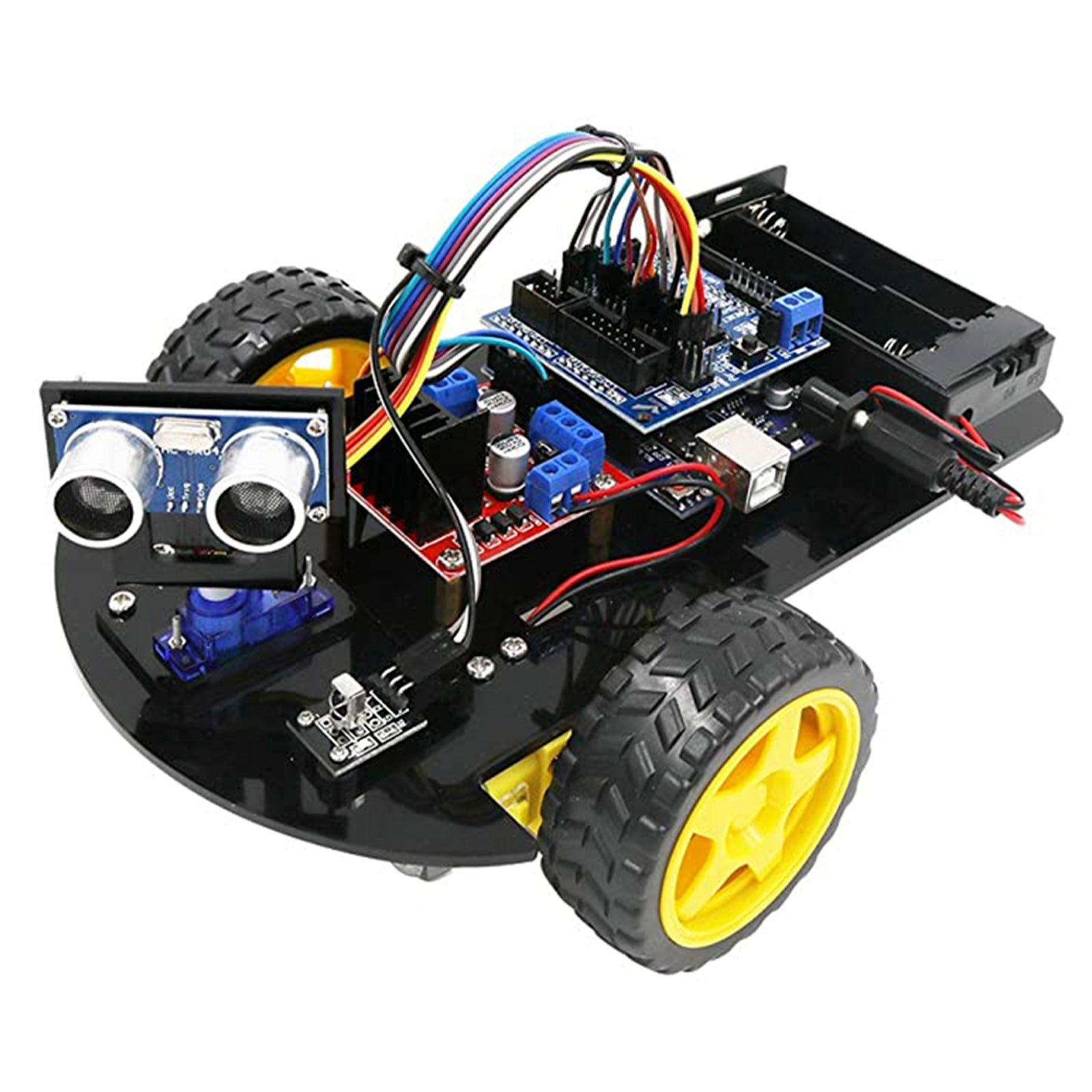
Finally, I tried the whole thing with an elaborate circuit. Even though I will only show an experimental setup with a breadboard in the following, it is an example of how to realize a fully functional circuit with the ATMEGA328 in a space-saving way, in this case for a Robot Car with the Motor Controller L293D and an IR remote control.
As a reminder here again is the pinout of the L293D:

From the example code we print here only the following snippet to understand the pinout. Otherwise I refer to our many contributions to the Robot Car topic.
// Motor pins
- int m1e = 10;
- int m11 = 9;
- int m12 = 8;
- int m2e = 5;
- int m21 = 7;
- int m22 = 6;


Here the link to download the sketch. Because of the IR remote control, the file PinDefinitionsAndMore.h (from the examples for the library IRremote By Armin Joachimsmeyer) must be saved in the same directory.
For further application possibilities I recommend our eBooks, the many blog posts as well as the above-mentioned Data sheet for the ATMEGA328P.




5 comments
StachelBanane
Ich hatte das gleiche Problem das bei unter 3,3V die CPU nichts mehr machte. Nach vielen herumsuchen habe ich festgestellt das ich den AVCC nicht mit Pluspol verbunden habe. Nach dem ich den auch verbunden hatte, siehe da ging es bis 2,7V runter. Bei Deiner Schaltung habe ich gesehen fehlt der 2te GND Anschluss, eventuell ist das Dein nicht kleiner als 3,3V Problem. Warum bei mir nicht kleiner als 2,7V geht, hängt mit dem Quarz zusammen, der schwingt unter 2,7V nicht mehr.
Gernot
@ Bernd und Andreas
Sehr schön , gefällt euch doch sicher auch so besser .
Macht weiter so .
Ich freue mich schon auf den nächsten Blog-Beitrag.
Schöne Grüße an Euch und das ganze AZ-Delivery-Team
PS: Ich persönlich stehe mehr auf Quarz-Oszillatoren. Hatte bei kritischeren Schaltungen mit einem normalen Quarz schon so meine Probleme.
Ja gut Quarz-Oszillatoren sind teurer , dafür aber äußerst frequenzstabil.
Wäre vielleicht etwas für den Shop . Ein Set mit Standartwerten , oder einzeln angeboten , mit 4,8,12,16,20, und 24Mhz käme sicher gut an.
Andreas Wolter
@Gernot: wir haben das Schaltbild aktualisiert und ausgetauscht.
Grüße,
Andreas Wolter
AZ-Delivery Blog
Bernd Albrecht
@ Gernot: Danke für das Lob und den Hinweis auf den Fehler im Schaltbild. Das wird ausgetauscht.
Gernot
Hallo !
Sehr schöner Beitrag.
Ich habe das Steckbrett-Schaltbild des Robot-Car’s zwar nur kurz überflogen , aber einen Fehler entdeckt , der angehende HobByelektroniker sicher verzweifeln lässt. ;)
Der Festspannungsregeler ist nicht richtig beschaltet , den GND-Pin auf Vcc zu legen wird nicht im Sinne des Erfinders sein.
Bitte überarbeite dahingehend das Steckbrett-Schaltbild nochmal.
Sei bitte auch so nett und füge die Kondensatoren für den Quarz hinzu . Es gibt nämlich viele verschiedene Hersteller und nicht jeder Quarz fängt ohne Kondensatoren zu schwingen an , das kann auch schon bei der selben Charge passieren.
Ich weiß , du hast oben darauf hingewiesen , daß Kondensatoren lt. Datenblatt benötigt werden , aber ein Bild sagt bekanntlich mehr als tausend Worte aus dem Datenblatt. ( lol )
Das könnte vielen Leute Haare kosten.
Danke und schönen Gruß.